
Creating Waves of Change With AI
Catch defects on the line. Stop failures before they stop you.
We inspect products with machine vision and watch your equipment with wireless sensors.
On site
Understand the line.
Decide with data.
Machine vision · Equipment monitoring
For roll-to-roll material production
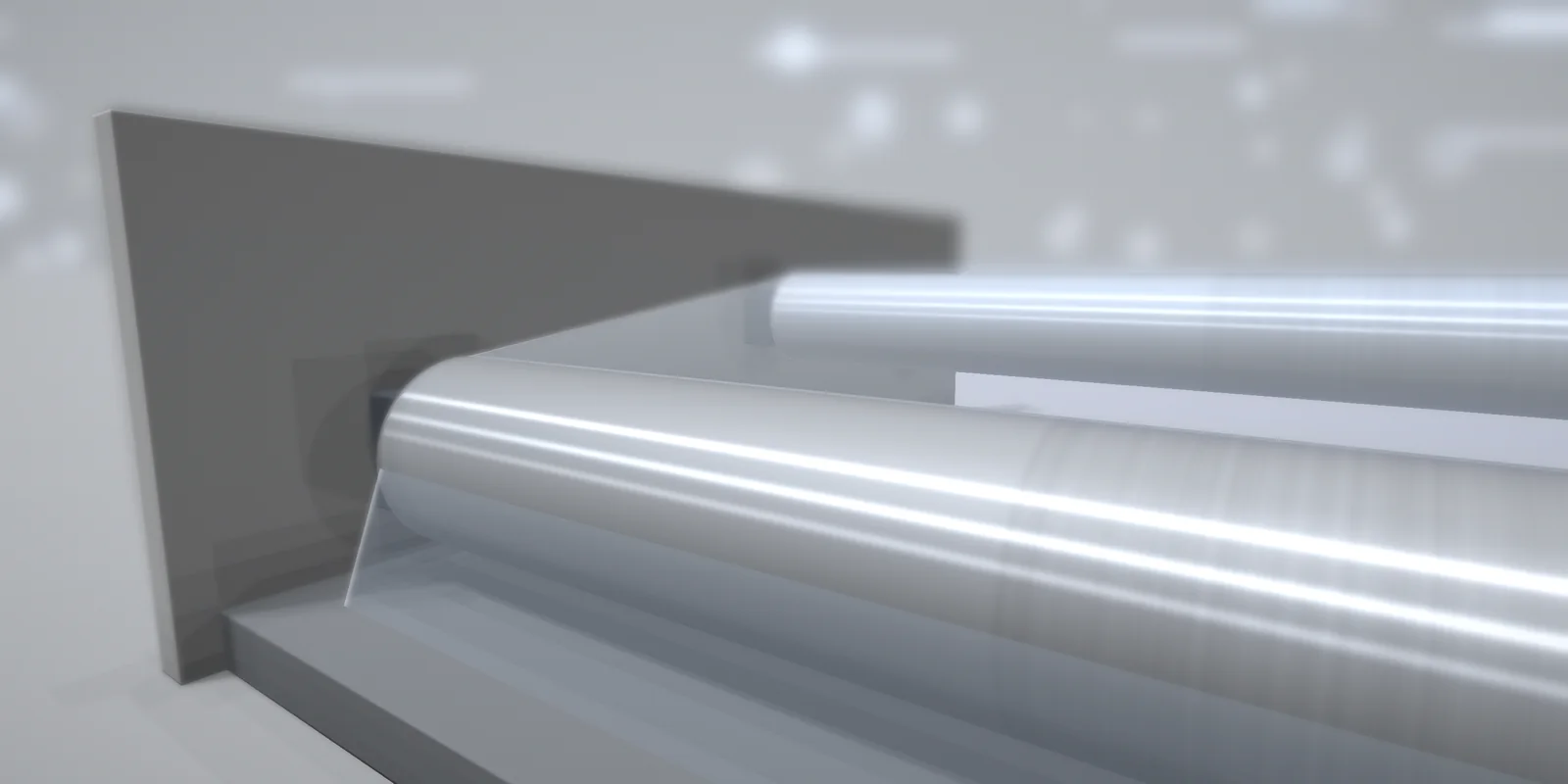 Inspection point · film surface
Measuring point · bearing housing
- Optical filmParticles, scratches and stains on thin, transparent film
- Battery separatorParticles and wrinkles on the surface, plus roll condition
- Copper foilDents and scratches on the surface, plus roll condition
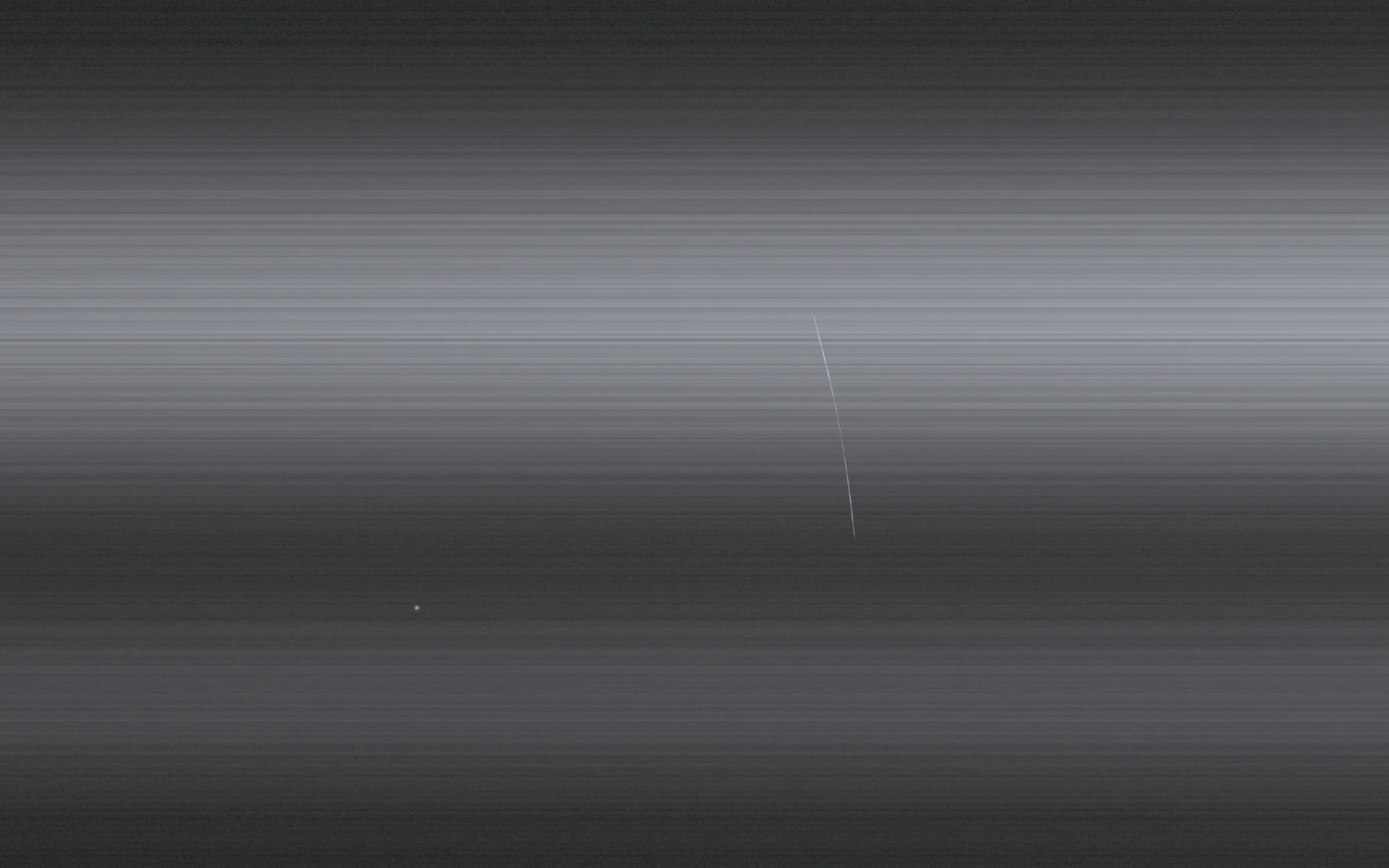
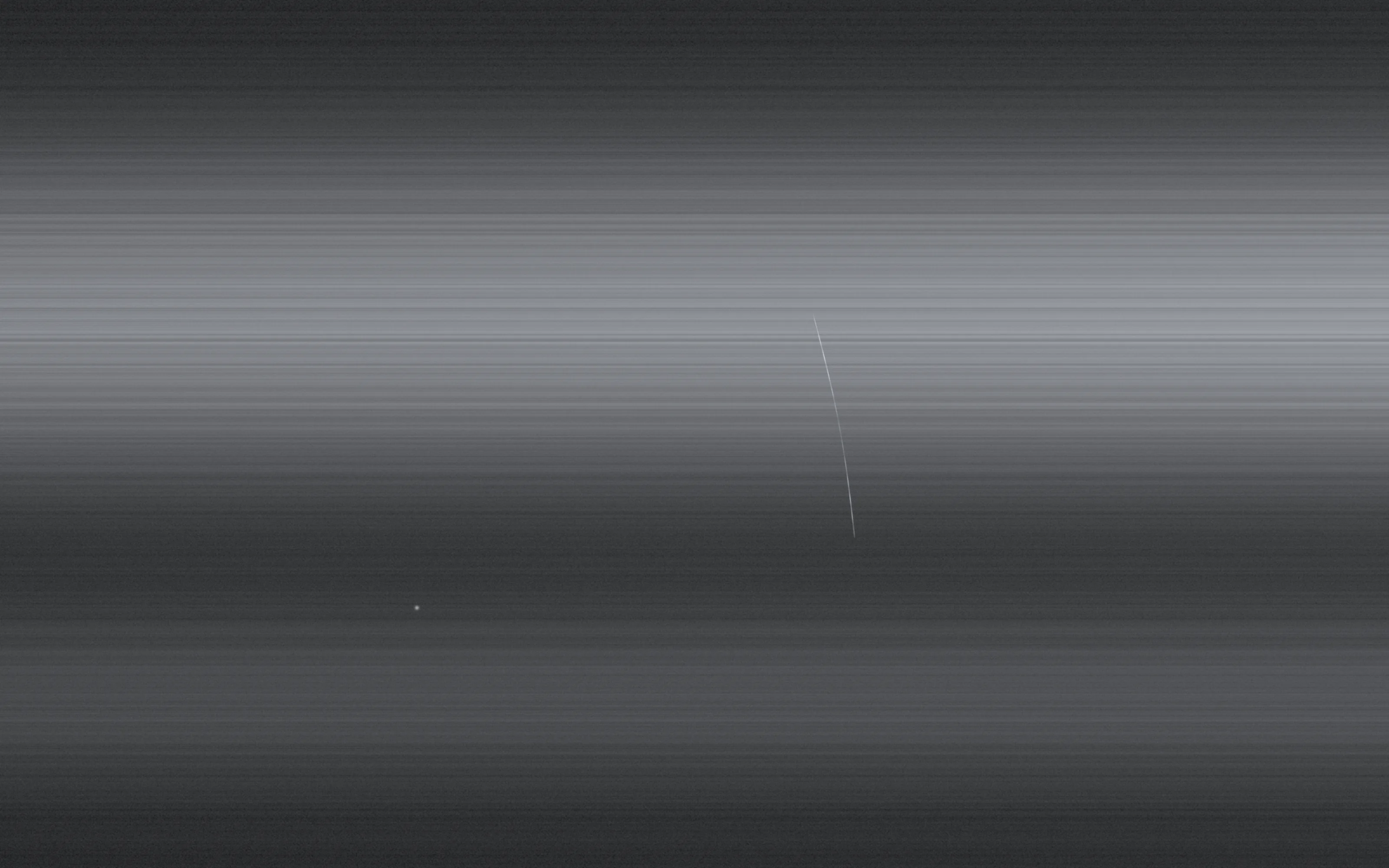 Scratch
Differences you can't see,
turned into data you can measure.
On uniform surfaces like optical film or copper foil, a single small mark is a defect. We set up lighting and cameras for the material to capture differences the eye barely sees.
Locate tiny defects
and see their shape.
Every defect found is logged with its position, size and shape, and sorted by type: scratch, white spot, particle and so on.
See the original
and the detection together.
Where the defect sits in the full frame and what it looks like up close, on one screen. The records help trace which process step caused it.
Explore inspection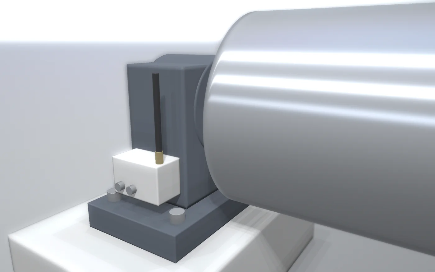 RotationRoll end · non-contact optical
VibrationHousing · 3-axis MEMS accelerometer
RMS-ONRoll monitoring
Demo screen| Roll | Status | Latest event |
|---|---|---|
| R1 | Normal | — |
| R2 | Check | Vibration change |
| R3 | Normal | — |
Every guide roll,
at a glance.
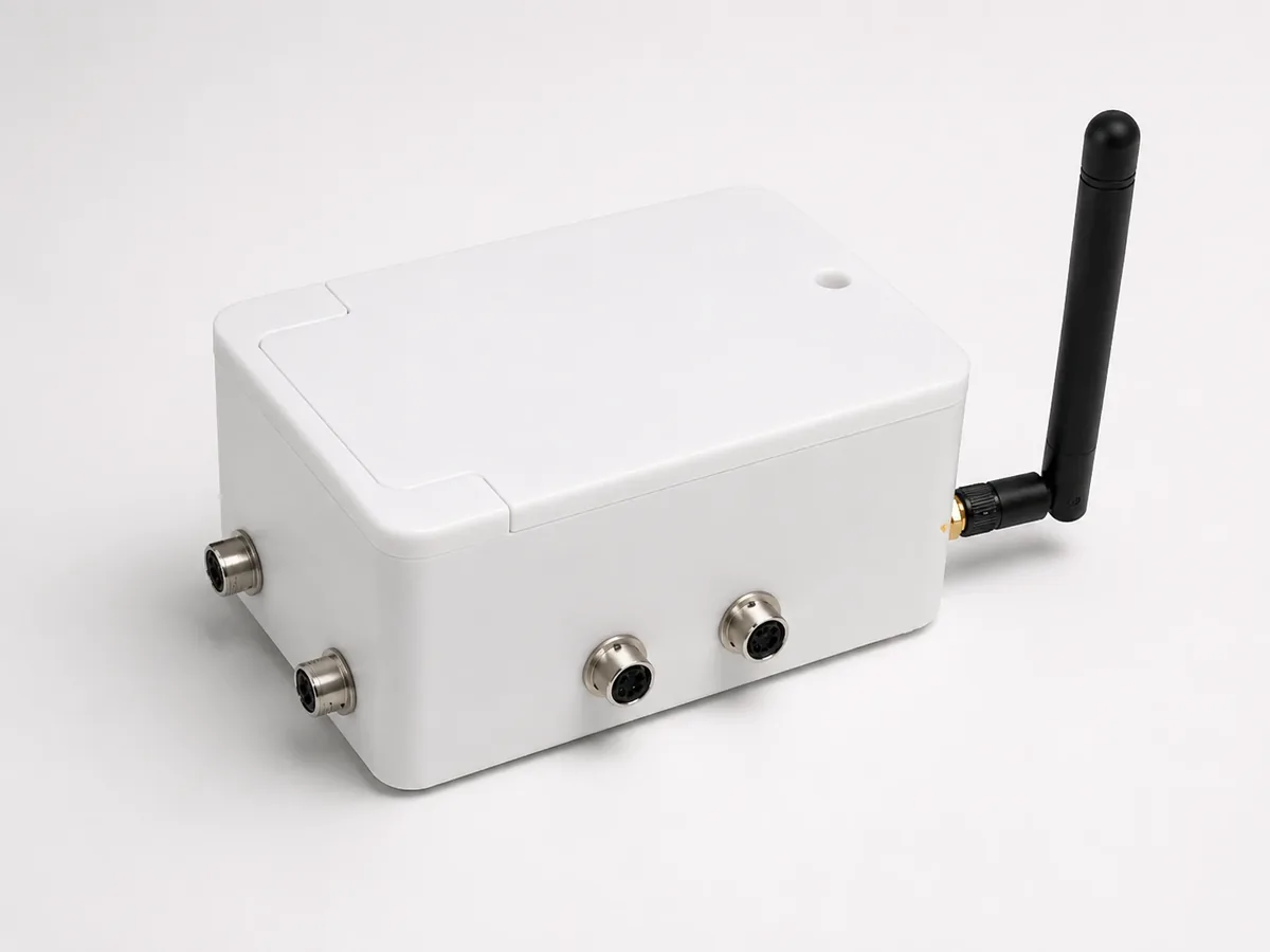
RMS-ON Edge mounts like a module on the fixed support that holds the roll. It is a battery-powered wireless node, so no cabling work is needed.
Rotation and vibration
show how equipment changes.
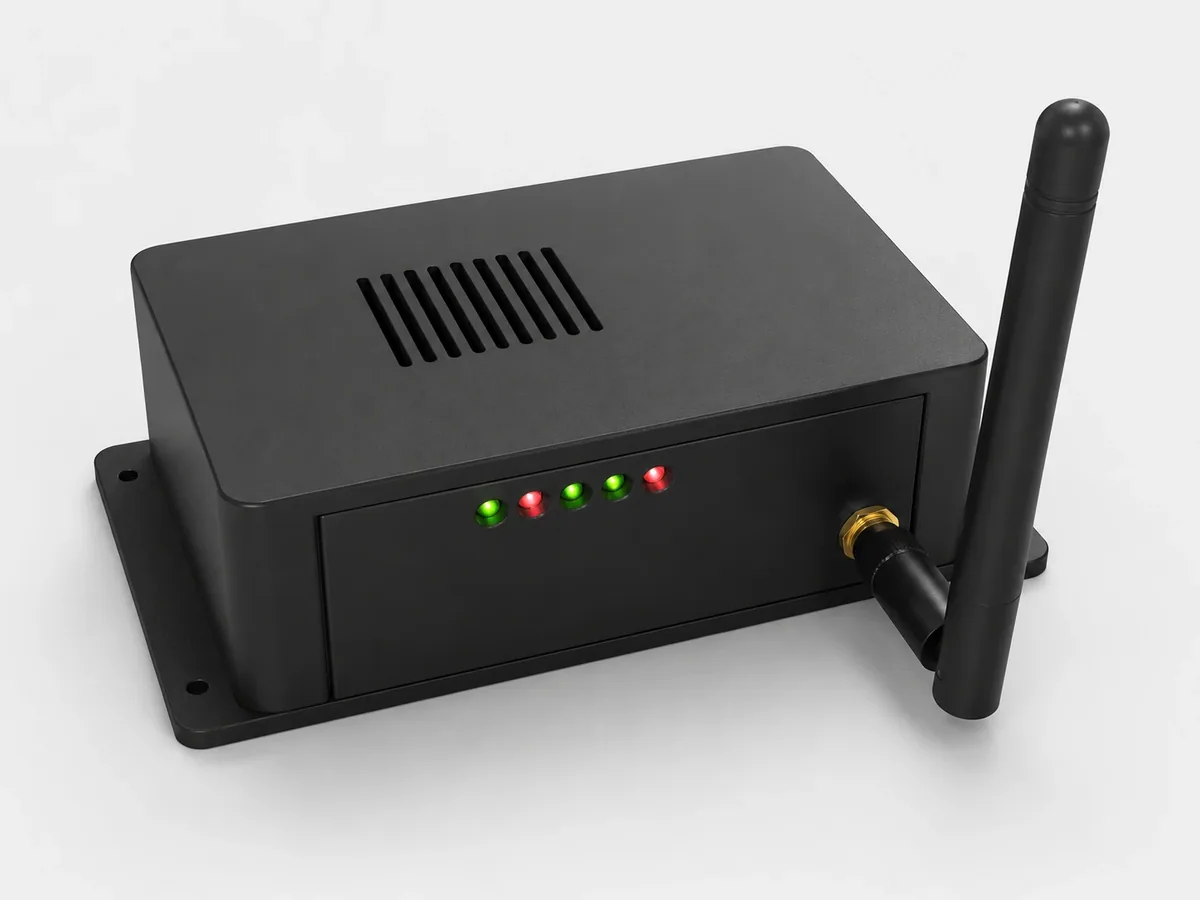
A non-contact optical sensor measures RPM and a 3-axis MEMS accelerometer measures vibration. Readings are collected at the gateway over Zigbee.
From readings
to maintenance decisions.
When a roll starts behaving differently from normal, it is flagged right away, so you can see which roll to check first.
More about RMS-ONDevelopment · Validation
The surest way
to explain technology.
We build it and measure it ourselves. Industrial cameras, lighting, sensors and MCUs are wired together and checked under real line conditions.
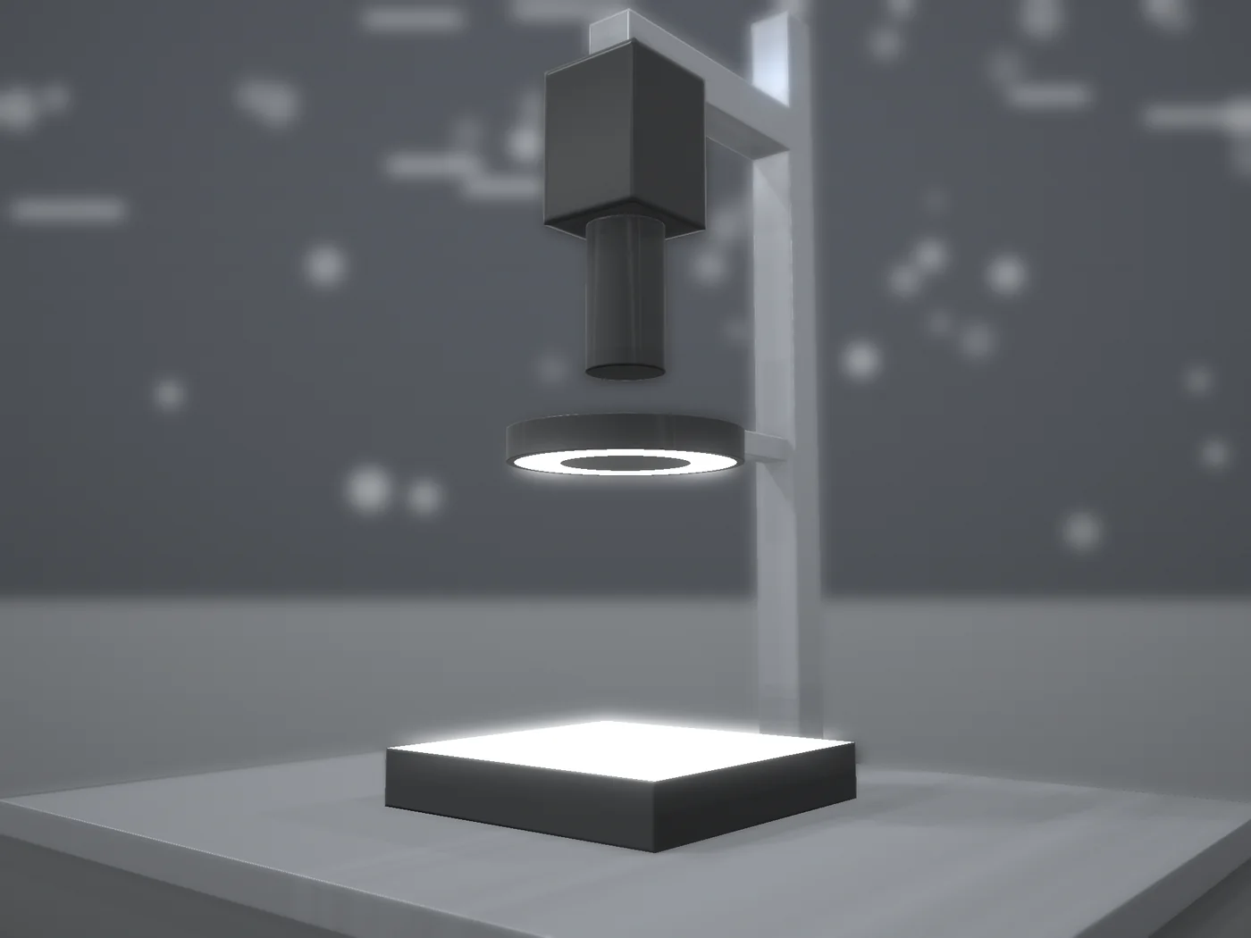 Generated example image
It starts with a sample test
- 01Sample testSend us samples and we check whether the defects can be detected.
- 02Site visitWe look at line speed, installation space and lighting in person.
- 03PilotWe install on part of the line and review real results with you.
- 04Rollout and supportAfter rollout, we keep tuning inspection criteria and models.